

ElectricMotorcycleForum.com

  • September 02, 2026, 05:07:40 PM
  • Welcome, Guest
Please login or register.

Login with username, password and session length
Advanced search  

News:

Electric Motorcycle Forum is live!

Show Posts

This section allows you to view all posts made by this member. Note that you can only see posts made in areas you currently have access to.

Messages - colillon

Pages: [1] 2
1
Ah interesting. When I had measured, I believe that they shut off due to no load, but I think that was a mistake on my side. I really don't think these shut off with no load.

I don't know exactly what you mean by Can power and Can gnd. On which "battery connector"?

Does the CCU have a CAN connection?

(I only checked with the diagram, not on my bike.)
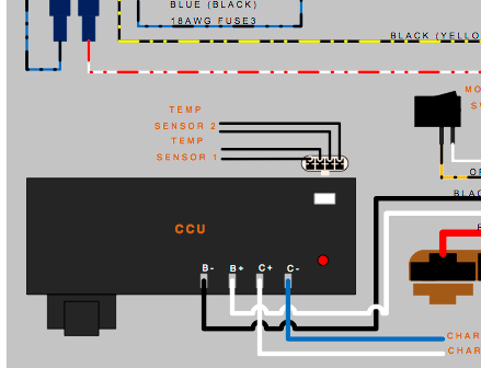
:)

hello again, here I am attaching a copy of the diagram where you can see the can bus lines (I have left them marked in the image), in the battery connector and the ccu, my question is whether or not there should be current in the can power line with the motorcycle off

2
Hey,
the infinite clicking is a bit unusual. I had taken those chargers out of the bike and powered them. This means they were not connected to a battery or other load, just like in your scenario where the contactor never closes. Still, there was no infinite clicking. They just started to power up, detected no load and shut down I if I remember correctly (they are Meanwell HLG LED Drivers for the 2013). Anyway this should be unrelated to your problem.
More tests... I have disconnected my onboard charger from the CCU (you were right, this charger only has a 220ac connection and a 116dc charging output, no other connection) and when I connect it, despite the fact that the click, click, click continues to be heard endlessly, it gives The 116v output perfectly and does not cut off at any time (without load, only the voltmeter connected)
Another test that I have done is to measure the voltage of the lines Can power 5v (red cable in battery connector or CCU) Can gnd (black cable) and I have no voltage, 0v; Should there be voltage on this line with the motorcycle off? when connecting to 220ac to charge I don't have the 5v of the Can line either

3
New measurement tests in the contactor area.....
Trying to clarify exactly where my problem comes from today I have been taking measurements in the area of the contactor and I have found something quite strange, let me explain:
With the battery pack connector disconnected from the motorcycle (in theory there is nothing connected to the battery at this time)
Two cables arrive at the contactor, one white and the other orange-gray (b+ low battery) with the tip of the multimeter positive in the orange-gray and the negative in the 300A mega fuse I have a reading of 103v... but putting the tip positive in the white wire of the contactor and negative in the 300A mega fuse I have a reading of 102v (exactly 1v less)
Knowing that the contactor works with 12v DC, this white wire should not have positive voltage, right?
If someone could check it or tell me if it's normal or not, I think I could start to know if my bms is defective or not and how to repair it

4
Hey,
the infinite clicking is a bit unusual. I had taken those chargers out of the bike and powered them. This means they were not connected to a battery or other load, just like in your scenario where the contactor never closes. Still, there was no infinite clicking. They just started to power up, detected no load and shut down I if I remember correctly (they are Meanwell HLG LED Drivers for the 2013). Anyway this should be unrelated to your problem.

Ok, I'll try disconnecting the charger from the battery to see if it does the same thing as yours...
But this charging error does have to do with my ignition failure, correct me if I'm wrong, but if there is a short circuit or error in the bms, neither the battery charge nor the ignition of the motorcycle would work, as exactly happens to me .
I am going to try disconnecting the battery completely (releasing the connector pack) and measure voltages and aim in the contactor area... since I have some voltages here that I think are not correct... such as the connector of the contactor has two cables, one white and the other orange-gray, both have a connection to b+ low battery and I suppose it should only have the orange-gray
Does anyone have a clue about this?

5
Hello again, when I plug in to charge my motorcycle I don't hear one or two clicks as you say... you hear click, click, click infinitely, while it is connected to the current but it never starts charging.
Do you recommend that I first find out what activates the contactor, that is exactly what I am trying to find out.....and I go further...I am clear that the contactor is activated by the BMS, I have no doubt about that since the two wires that reach the contactor (orange-grey and white) come directly from the bms
What I do not know or am not very clear about is how the mbb and the onboard charger tell the bms to turn on the contactor...through which signal, I will review the post that you comment on to see if I clarify something else.
Giving up or not with the motorcycle does not depend on me, this motorcycle is not my property and even so I have been working for free on it for almost a year, this motorcycle came to repair the dcdc and before trying to repair it while in my workshop it stopped working. work completely....with what suddenly became my personal problem

6
As you commented in your previous message... The contactor is controlled by the MBB???
Well, it's a very good question, after reviewing schematics for other Zero models for thousands of hours and the existing schematic for 2013; of course, also taking measurements on the motorcycle itself and disassembling it almost completely....... even so, it is not very clear to me "what controls what, when and how"; but I have some suspicions, if someone confirms or denies them, it would be a great advance.
I think the starting of the bike goes more or less in this order...the key switch connects a pin with B- to another pin on the MBB(red and white wire) to activate the ignition and I guess the mbb with "some voltage or signal" tells the bms to activate the contactor and sends "another signal" to the sevcom to activate the motor... but since I don't know what type of signal or voltage has to be produced for it to work or how the bms has to respond to activate the contactor i can't figure out the fault.
I deduce that my problem is in the bms because apart from the start-up, the charge also fails (onboard charger).
When I plug it in to charge, a soft click-click-click is heard in the lower area of ??the battery (where the charger is located) and it does not close the contactor to charge the battery.
From what I have been able to find out, I think that both when turning on and when charging, the mbb needs some type of response from the bms or vice versa and it is not happening... knowing the necessary voltages or signals could theoretically fool the mbb so that he believed that the bms is fine and turned everything on.


I have all kinds of measurements; with key switch on, off, in outputs and inputs of the bms, ccu, mbb, sevcom, contactor etc... if someone thinks they can help me I can provide all the information they need, as I mentioned in my first message there is a video on youtube of a 2015 zero ds working perfectly with the broken BMS and also marking an error on the board, simply canceling and replacing some signals, but it does not explain which signals it replaces (the person in the video had two bms motherboards, one in good condition and that is why he was able to know the necessary tensions) and does not respond to emails either

7
Mmh okay I understand your problem now, but I don't have enough knowledge to really help I think.
Is the contactor controlled by the MBB? I know that there is some programming in the Sevcon for that, not sure which way Zero took.
I think you'd need professional help from Zero here.

Since I have a 2013 S with access to the MBB, BMS and Sevcon, let me know if you want me to confirm something.

First of all, thank you very much for your help, very few people are capable of trying to help even when they are not very clear on how to do it.
I wish I had professional help from Zero, even if it was minimal, in my city (Tenerife) the official Zero dealer does not want to pick up my motorcycle since according to them it has been "tampered with". The official service that sold me the new MBB (in another part of Spain) has no knowledge of this zero model either or they don't want to help me.
I have sent emails to "professionals" in other countries at the official zero service and the only thing they tell me is to take my motorcycle to an official dealer or they do not answer me directly.
I am an electronic engineer and I have had an electronic laboratory for more than 20 years. If I had the necessary information or technical data, I could repair the motorcycle and find out where the problem is specifically. Unfortunately with the data that is published in this forum about the zero 2013 ds I can't figure it out. I've been having this problem for more than 10 months and no solution

8
Thank you very much for answering, a short circuit in my dcdc broke my mbb, I have not changed the dcdc because I have been able to repair it, now the dcdc (normally activated by the mbb enable signal) is disconnected from the mbb and I turn it on with an auxiliary relay, If you look at my message, I explain that the ignition and power voltages reach the mbb but it does not turn on (it does not output an enable signal, nor does it activate the contactor)
The lights, indicators, horn etc are a separate 12v circuit, and this works perfectly, I can turn it on and off at will.
What does not work is charging or riding the motorcycle, since the mbb does not activate the contactor & It does not give any enable signal either (to the dcdc or to the battery charger), I suppose due to the lack of some voltage coming from the bms (just these voltages are what I am trying to find out)

9
Zero Motorcycles Forum | 2013+ / 2013ds bms voltages, signals??any ideas??
« on: November 21, 2022, 11:08:45 PM »
Hello everyone, I have a zero ds from 2013, with a 9.4kw battery. Due to an error in the dcdc my MBB died. I have ordered a new Mbb from an official zero dealer, this mbb is supposed to come programmed and ready to work, but when I mount it on the motorcycle, it does not turn on :'(
I have been doing voltage checks and others... the battery voltage is correct and reaches the mbb perfectly, the ignition signal from the contact works (checked in the mbb connector)
I do a test to the bms and the result is correct,I have also tried a hard reset with the bms buttons, but it has not solved the problem.
I think the problem is that my bms is defective and there is some voltage or signal that does not reach the bms to the mbb and for that reason the mbb does not turn on.
Does anyone know the bms connections to activate the mbb? I have seen people who with a broken bms manage to trick the mbb into believing that everything is correct and they make the motorcycle work.

Another thing that I have tested is the contactor, if I supply it with 12v it works perfectly

I APPRECIATE any help or test you can do, if someone knows the signs that I have to look for or replace it would save me

10
I suspect it has something to do with the key on input to the MBB among possibly other things. There's a schematic for a 2016 model floating around that doesn't show the lower power B+ fuse else this would be easy. However, there is already a 4-amp fuse on the 100v line to the MBB and various 12-volt fuses coming off the DC-DC converter to the standard automotive accessories like the lights, indicators, dash, etc.

When I remove the low power B+ fuse, the dash doesn't even come on. Given that the dash receives power directly from the DC-DC converter through an ATC fuse (and I doubt Zero would have doubled down on the fusing in the same wire), I have to conclude that the low power B+ fuse breaks the key on input signal to the MBB, which the MBB would use to enable the DC-DC converter.

Next chance I get, I'll probe the voltages at the fuse key on and off relative to B-. Key off I think it was about 7-1/2 volts, which is an odd value.

Thanks for participating in the post, the assumptions of how the low power fuse b+ works or what they say in the manual about how to place the fuse, I have them clear, but I have realized that nobody really knows what this fuse really protects, I have made thousands of measurements and there is only one power line for the mbb from the bms and it is pin 7 and 18, low power line b+ and b-. My idea was the same that that fuse would protect the power supply of the mbb on pin 7 and that when removing or melting that fuse it would stop feeding that pin (then the mbb takes those 110v and takes them out through the enable pin that goes to the dcdc to turn on the 12v part)....the problem I find is that when I remove the low power battery b+ fuse I still have power to the 110v mbb (pins 7 and 18)

With the main contactor of the battery off, that low power circuit is the only power supply, otherwise you won't be able to turn the bike on again, so yes, directly from the battery trough that low power b+ fuse, the BMS is powered (to log what's happening with the battery, and be able to turn the main contactor on when requested by the MBB, or charger), and also the MBB will get power to be able to turn the bike on.
That little fuse is very important, and it can ruin your day :D

I REPEAT AGAIN SINCE I SEE THAT IT IS NOT CLEAR:
Thank you very much again for participating, but either I have not been able to express myself or I am not being understood for some reason... if that fuse we are talking about protects the power line of the mbb, why by removing it I still have power in the mbb?? In other words, without that fuse connected, I still have 110v power on my mbb between pins 7 and 18 (normally it is powered on these pins).

11
Hello again everyone, I have a zero ds from 2013 with the mbb burned (already checked) the bms is apparently perfect, it responds well to the tests and between pins 7 and 18 of the mbb I have the corresponding 110v....before to assemble the new mbb (I haven't managed it yet) I want to check the tensions well so as not to burn the new mbb.
My main question is if anyone really knows what this Low Power B+ fuse protects? with the broken mbb that fuse broke when plugging it in, but now being on or off i still have 110v between pins 7 and 18 of the mbb, shouldn't that power be cut off when removing the fuse?? Does anyone know where this problem could come from?

Try looking here: https://zeromanual.com/wiki/Main_Page

Thank you for your message, but I have reviewed all the wiki and forum posts...I've been looking for information about it for weeks, I've even asked "experts" from the official zero motorcycles house and no one has been able to answer me clearly, everyone world refer me to the manual (nothing is explained on the subject) or they tell me their opinion without being completely sure.

12
I suspect it has something to do with the key on input to the MBB among possibly other things. There's a schematic for a 2016 model floating around that doesn't show the lower power B+ fuse else this would be easy. However, there is already a 4-amp fuse on the 100v line to the MBB and various 12-volt fuses coming off the DC-DC converter to the standard automotive accessories like the lights, indicators, dash, etc.

When I remove the low power B+ fuse, the dash doesn't even come on. Given that the dash receives power directly from the DC-DC converter through an ATC fuse (and I doubt Zero would have doubled down on the fusing in the same wire), I have to conclude that the low power B+ fuse breaks the key on input signal to the MBB, which the MBB would use to enable the DC-DC converter.

Next chance I get, I'll probe the voltages at the fuse key on and off relative to B-. Key off I think it was about 7-1/2 volts, which is an odd value.

Thanks for participating in the post, the assumptions of how the low power fuse b+ works or what they say in the manual about how to place the fuse, I have them clear, but I have realized that nobody really knows what this fuse really protects, I have made thousands of measurements and there is only one power line for the mbb from the bms and it is pin 7 and 18, low power line b+ and b-. My idea was the same that that fuse would protect the power supply of the mbb on pin 7 and that when removing or melting that fuse it would stop feeding that pin (then the mbb takes those 110v and takes them out through the enable pin that goes to the dcdc to turn on the 12v part)....the problem I find is that when I remove the low power battery b+ fuse I still have power to the 110v mbb (pins 7 and 18)

13
Hello again everyone, I have a zero ds from 2013 with the mbb burned (already checked) the bms is apparently perfect, it responds well to the tests and between pins 7 and 18 of the mbb I have the corresponding 110v....before to assemble the new mbb (I haven't managed it yet) I want to check the tensions well so as not to burn the new mbb.
My main question is if anyone really knows what this Low Power B+ fuse protects? with the broken mbb that fuse broke when plugging it in, but now being on or off i still have 110v between pins 7 and 18 of the mbb, shouldn't that power be cut off when removing the fuse?? Does anyone know where this problem could come from?

14
Something that I had forgotten to comment on is that the short circuit that generated the problem was between the enable signal coming from the mbb to pin 1 of the dcdc and the signal b-

15
I would check the ignition circuit on the BMS and make sure it is still generating the 12V as expected. The BMS generates its own 12V via its own regulator. I've seen the DCDC damage that circuit on the BMS, despite the BMS checking out on serial and via testing. Sometimes that kills the MBB as well.

Unfortunately I think the MBB and BMS will be difficult for you to repair if they are defective. They are both potted in a resin to prevent water ingress, and I know of no good way to access the components. Schematics are also not available, and neither are the bootloaders for the chips.

Odds are it would be cheaper and less time consuming to get new parts. Perhaps Zero US could help, but I'm not sure there's much they'd be willing to do.

Thank you very much Auriga for your answer, are you sure that in this specific model the bms also generates 12v voltage? I suppose that 12v voltage will go to feed some part of the mbb, since the dcdc does not feed the mbb, would you know what pins the 12v carry in the 12-pin connector that comes out of the bms ??? To be able to test whether or not I have those 12v and the bms is fine at all, it would also help me to know the pins where they would have to connect those 12v that you mention in the mbb (34-pin or 40-pin connector) in the diagrams that I have found they do not appear tensions and the verification becomes quite difficult ..... I have already tried to speak with zero official in the usa, but they ignore me

Pages: [1] 2