I guess it is about time I start to mirror content over here to engage those who don't use FB (and I don't blame you

)
There are three ways to follow my progress in the order I will likely update them.
1) Zero Motorcycles Owners Group on Facebook
2) My Flickr feed Vetterizing Album
https://www.flickr.com/photos/71805301@N05/sets/72157643430171885 (Oldest images are on top and it is over one page now)
3) Here

So lets get started. I should note I am trying to do this without use of a computer though a final design will be created on one. It is hard to take an image, correct for distortion, scale it, then transfer to a computer, print out a scale drawing, compare to bike etc ...
So I am using several techniques some of you have heard me use before.
CAD (Cardboard Aided Design)
TAD (Tape Aided Design)
PAD (Plywood Aided Design)
Typically the order of operation is TAD > CAD > PAD
TAD I typically will use to transfer holes on the bike to a 2D format I can move around.
CAD is typically used for general mockups and may or may not reference TAD to make more accurate.
PAD is used as the last step before transferring the design to metal. It uses both the TAD and CAD mockups to confirm before cutting.
The final design is going to feature two large 1/4" - 3/8" plates on either side of the bike and everything will be mounted from these plates. Another plate will be found under the turret.
I am not going "Terry Hershner" on the bike just yet and cutting the "horns" off the bike. I put a informal poll on the FB group and it seemed there was interest in turning one of Craig Vetter's mockups of a 2015 bike into reality. I will build this version first with stock seating then move into lowering the seating position later.
And now ... on to the images and captions (all of which were pulled from my FB posts, transferred to the flickr feed, then posted here
so you are not missing out)
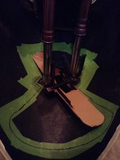
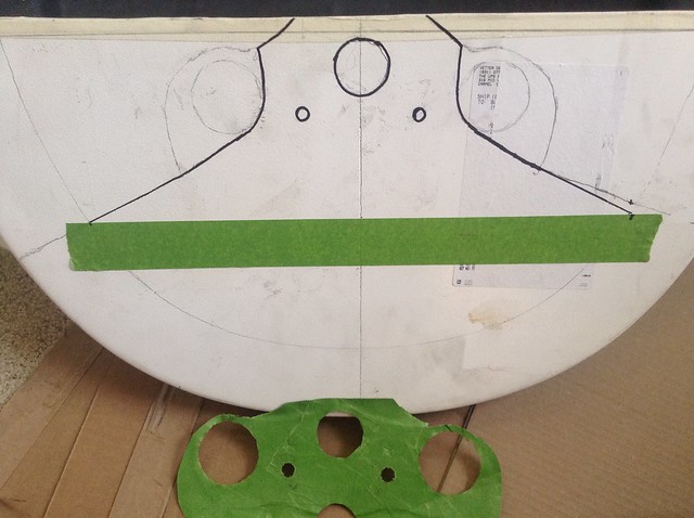
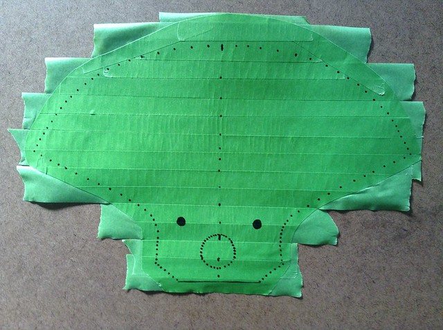
Smilie is drawn!Figuring out wheel clearance. I went back two more times to make sure this was accurate for what I require. 1" clearance at nose and tapers toward ends for slower speeds.
 CAD plus tape
Cardborad Aided Design expanded to figuring out where I need to cut for stock seating position.
 TAD/CAD
Using Tap Aided Design and Cardboard Aided Design to figure out placement on turret for trimming and plate construction.
 Cleco clamps
These things are great! Using them with a small strip of wood and some tape near the noes to hold things together for mockup.
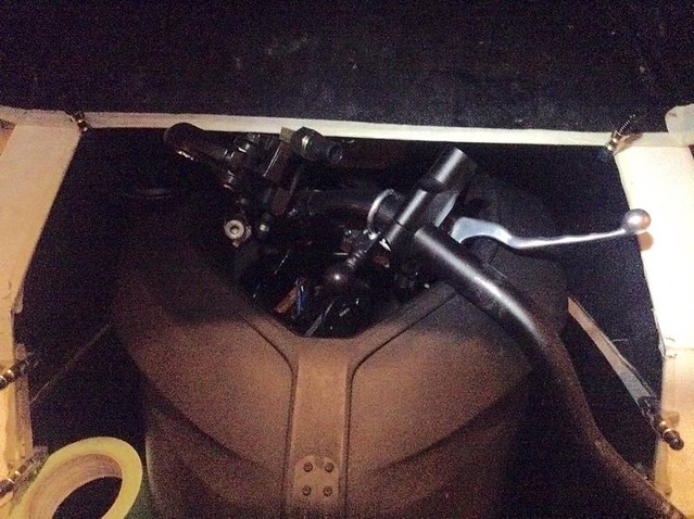
 Nose and sides level
This is where the turret would be with the nose 6" from the wheel and both halves put together. 6" up and 4" back of a normal handlebar position.
 Nose Clearance
Small piece of cardboard down there is the wheel mockup. You want 6" of clearance between tire and nose
 First round stock seating
This was done to see what would need to be trimmed if the upper cowl lip was set level with where I thought I needed it to be. I was wrong mind you.
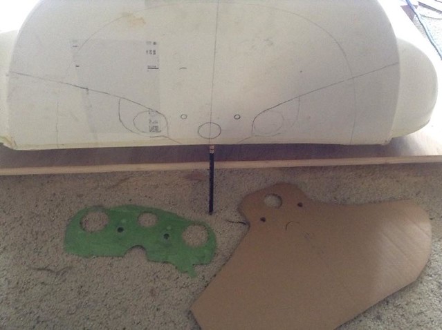
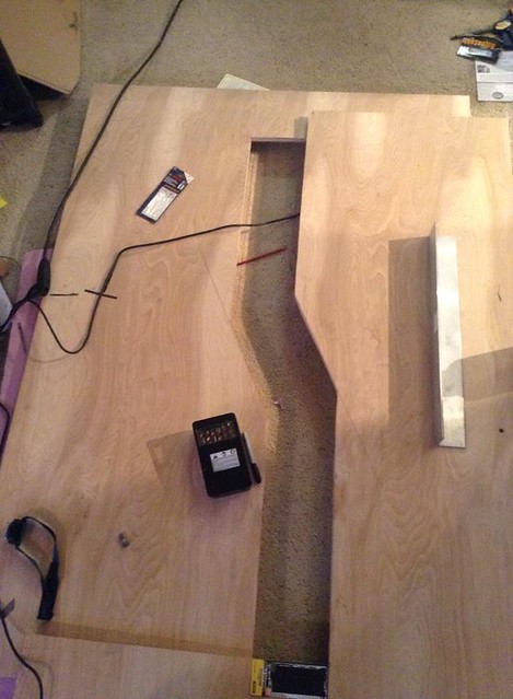
 Plates cut and PAD
Plywood aided design extended from CAD (not pictured) I will use to mount the preliminary cowl / tail etc before going to metal.
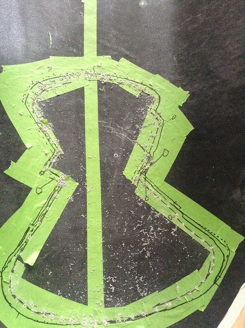
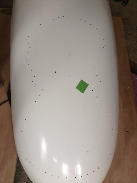
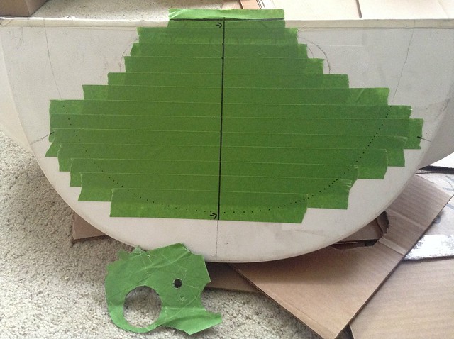
 Smilie guideline drilled
Drilling guidelines for lower vetter cowl. If you look closely there are two sets of lines. One set is exact and the other is one inch from wheel. The final line tappers between the two with the one inch towards center and exact on outside.
 Reverse side
I will cut from this side on outside edge
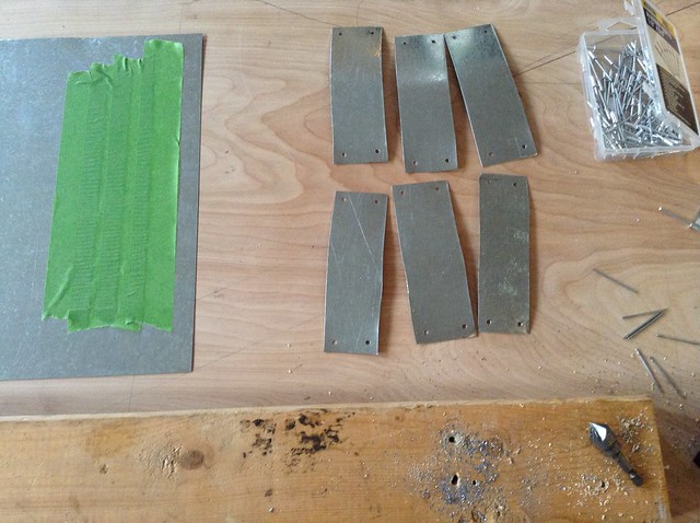
 Assebly line
Tape to left is 4" wide. I start cutting a long strip from it with .5" on both sides then cut these smaller strips then drill them and debur.
 Pop rivets and cleco clamps
Using cleco clamps to hold panels while I drill other holes.
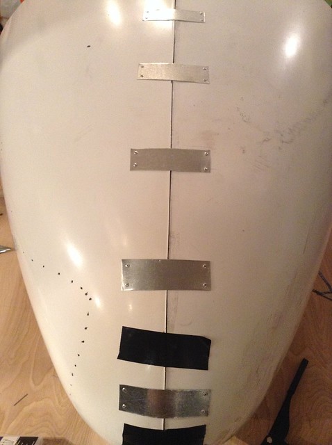
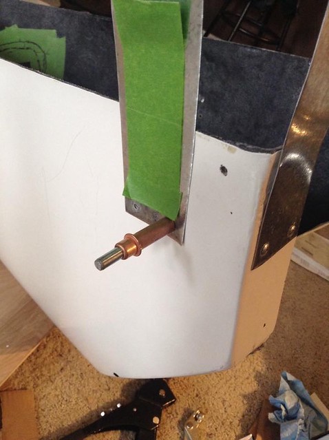 Riveting in Tabs
Adding tabs to connect bottom to top. They are about 5" and centered to edge of fiberglass.
 Squaring off final cut
Design was not square to center. Notice top line is square to center and the right line was off.
 One side done
Wheel side / bottom cowl, finished. About 100 rivets total.
 Connecting both halves
Once side done, buttoning down other side. Gorilla tap there to help line stuff up in interim.
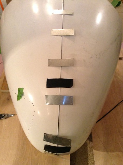 Connecting both halves
Final connections made.
 Connecting both halves
Note the dis-colorization near the edges is a sanded down taper on both sides about 2" in from edge. The rivets fall on outside of this so they don't get caught up in the resin.
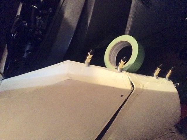
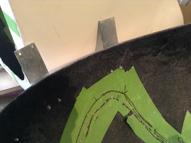
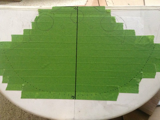
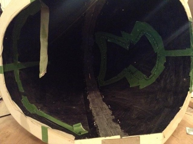 Taping up turret
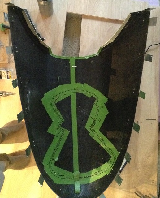
Taping up turret to transfer centered design to wood to test fit before metal.
Note the tape in center is first layer, that bit is important to pull it off in one piece. Also note the dots placed in spite of the next layer being placed over them.
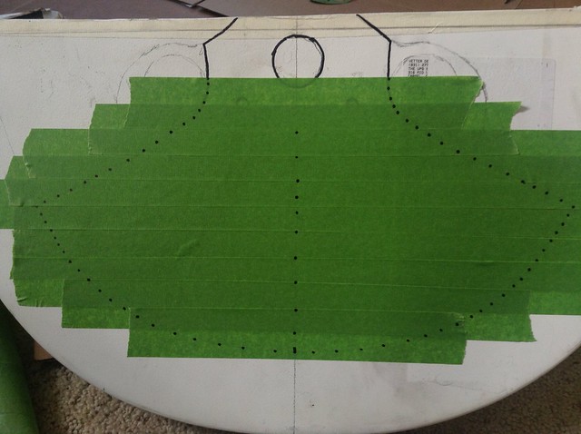 Final Tape Up
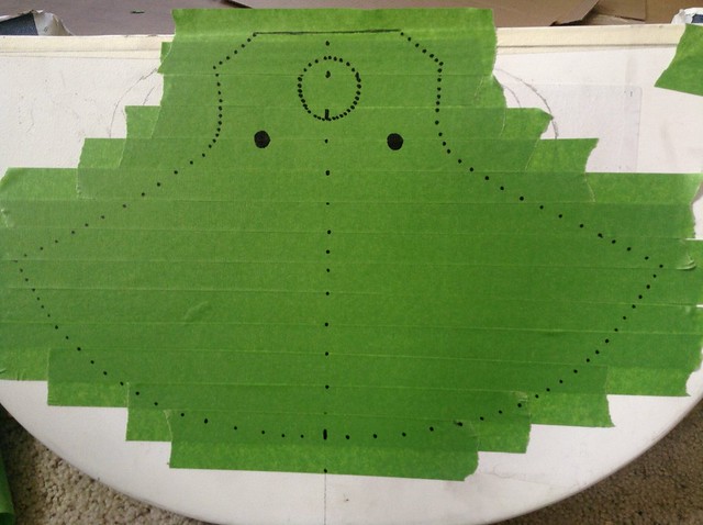 Trimming Tape
Trimming up for removal. Pulling from that first piece in center.
 Taping back side
There are now three layers of painters tape here
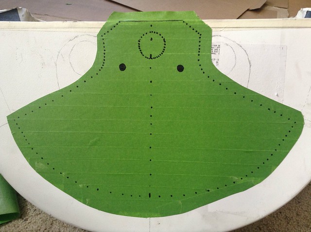
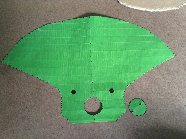
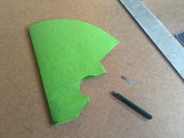
 Shape cut out of tape
Major hole cut out, shape cut out, and smaller holes have a center hole only for a punch
 Transferring Design
Transferring to particle board which is half the thickness of my plate
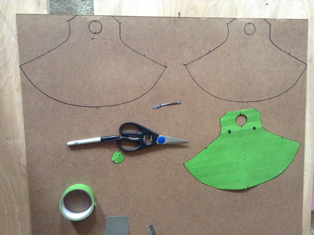 Cutting them out
You will note extra black marker though ... Turns out the shape isn't mirrored right. I already know what I need to do to get a uniform centered shape but it will have to wait till tomorrow where I will again cut out the particleboard shapes then glue together.
I wasn't thinking when I did this or I would have caught it before cutting >_< still looks like progress though
 Starting over
Starting over, same process as before but less information which isn't accurate. Note he arrows pointing to the side which has the centered edge.
 Transferring design
Design transferred but I am only interested in the left side
 Folding in half
Carefully folding it in half after applying more tape to back
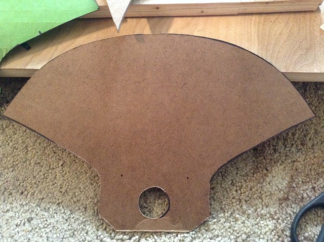
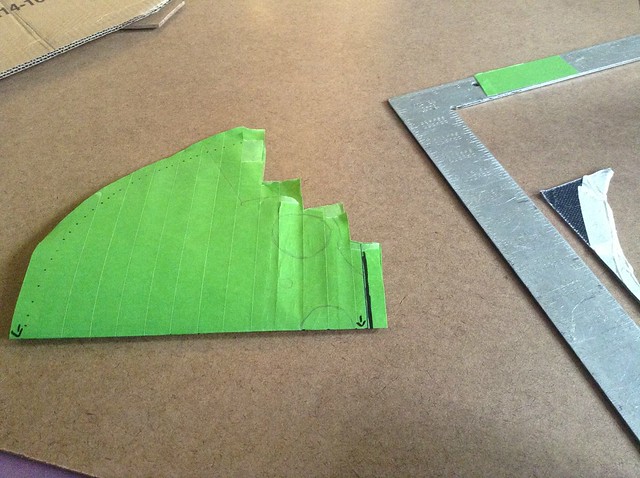 General shape cut
I went back with the razor blade and marked where fine tuning needed to occur. All cuts from one side this time.
 Testing against template
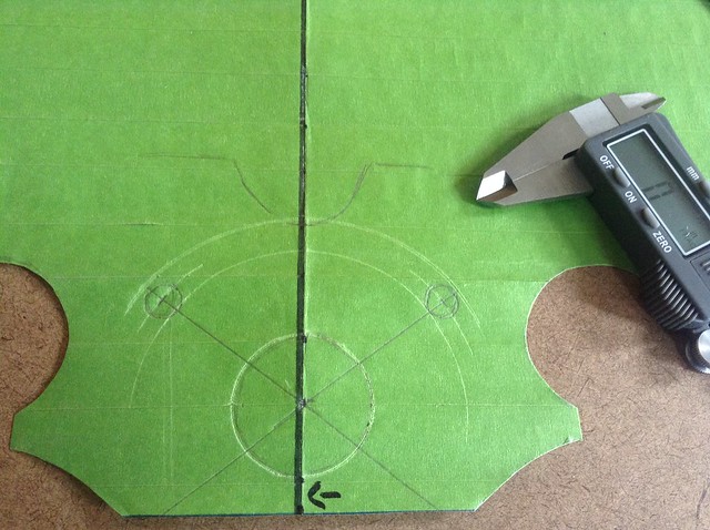
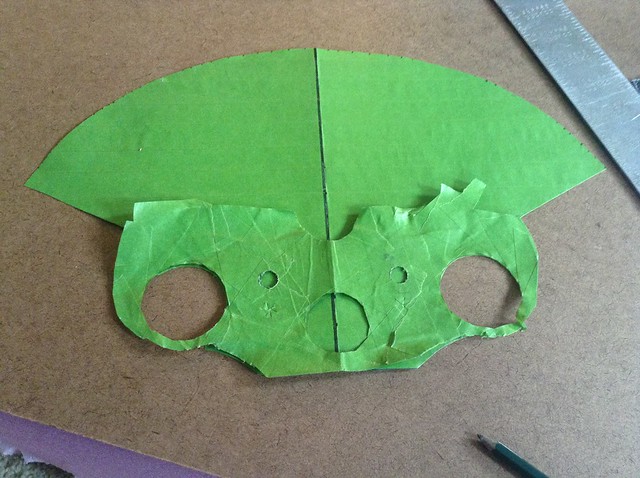 Getting Technical
Getting technical and marking center points, diameters, etc with calipers and straight edges.
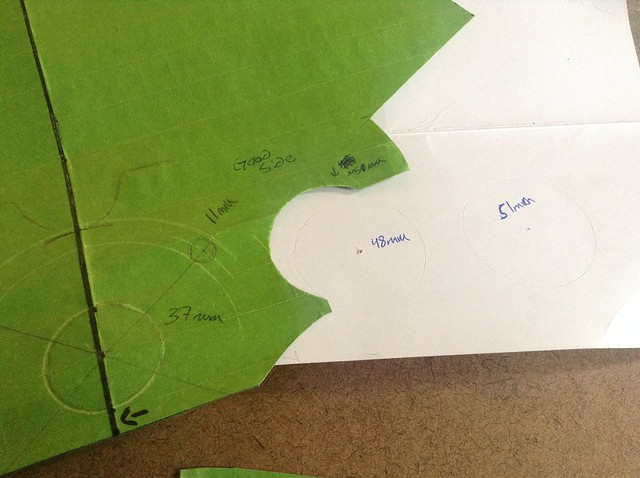
 Adding measurements
Adding measurements for reference and checking round of the down tube holes. Added .75mm to the radius to give a little room between plate and tubes.
Extra notes:
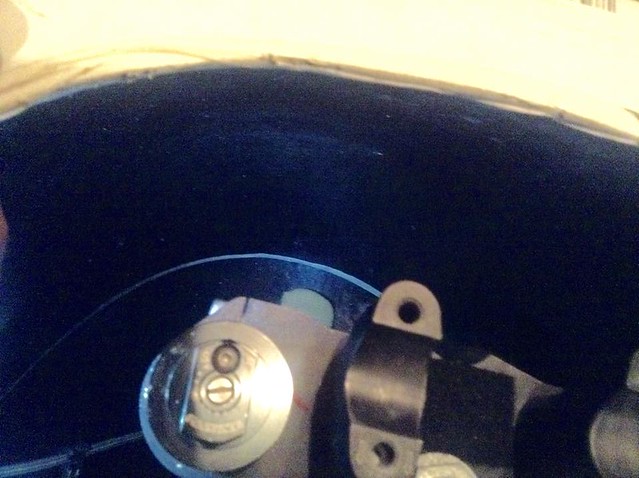
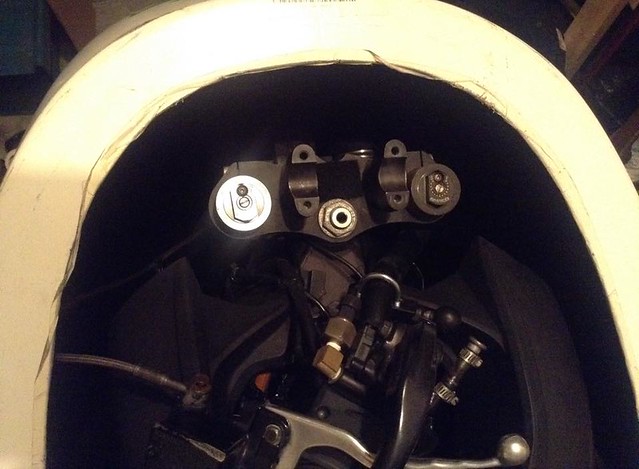
It seems the 2015 top of triple tree has the handle bar mounts fused to the tree ... on the 2013 this isn't the case. So my design wouldn't work with the 2015 less the design is modified and new mounting points chosen since I plan to use my handlebar mounts to secure the plate.


 Author
Topic: Vetterizing 2013 S Build (Image heavy!) (Read 1037 times)
Author
Topic: Vetterizing 2013 S Build (Image heavy!) (Read 1037 times)